contact lens case reports
Bringing Toric Soft Lenses Into Focus
BY PATRICK J. CAROLINE, FAAO,
FCLSA, & MARK P. ANDRÉ, FAAO, FCLSA
November 2001
We are aware that when the rotation marker of a toric soft lens positions to either side of 6 o'clock, a cross-cylinder effect takes place. The improper position of the lens frequently results in a decrease in visual acuity for the patient. What is amazing is the amount of confusion about what to do next. Part of the confusion is that there are multiple paths one can take to arrive at the same destination.
|
|
|
|
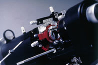
Figure 1. The lensometer
technique. |
|
Which Path to Take?
Path 1 is the LARS technique in which the position of the lens axis is adjusted (left or right) to line up with the eye's cylinder axis. The drawback is the number of variables that can affect the on-eye power of a toric lens, including cylinder masking and possible lacrimal lens effects (secondary to the thicker lens design), errors in vertexing the Rx to the corneal plane and lens draping effects over the underlying corneal topography. The sums of these effects can be discovered by performing a sphero-cylinder over-refraction (SCOR).
In Path 2, enter the contact lens Rx, the SCOR and the amount of lens rotation into a pre-programmed calculator or software, and calculate the cross-cylinder effects. Consider the direction and amount of lens rotation for correct resultant powers calculation.
In Path 3, place the contact lens sphere, cylinder and axis into a trial frame. Position the powers of the SCOR over the top and place the trial frame into the lensometer. The lens powers are read identically to those of a spectacle. Make sure the axis of the SCOR is appropriately positioned, as described in Table 1.
A Trial Run
Calculate the final lens powers using first the calculator, then the lensometer technique described in Table 1.
Example 1. OD
CL Rx: 4.50 2.75 x 175
Rotation: 20 degrees right
SCOR: +0.50 1.25 x 130
Example 2. OS
CL Rx: +3.50 1.75 x 95
Rotation: 20 degrees Left
SCOR: +0.50 1.50 x 140
Answers:
OD: 5.00 2.25 X 162
OS: +3.00 1.25 X 123
|
TABLE 1The Lensometer Technique |
|
STEP 1. Add the sphere powers of the soft lens and over-refraction and place that power into the back slot of the trial frame. STEP 2. Place the cylinder power of the contact lens into the trail frame and rotate the axis to the position indicated on the bottle or foil pack. STEP 3. The axis of the over-refraction cylinder is positioned as follows:
|
|
Patrick Caroline is an associate professor of optometry at Pacific University and an assistant professor of ophthalmology at the Oregon Health Sciences University.
Mark André is director of contact lens services at the Oregon Health Sciences University.


