TOPOGRAPHY AND ORTHO-K
Corneal Topography And
Orthokeratology: Post-fit Assessment
Corneal topography accurately diagnoses post-fitting problems of
ortho-k patients.
By John Mountford, Dip App Sc, FAAO,
FCLSA, and Don Noack, Dip Opt (WA)
Part I (April 2002) of this two-part series discussed the role of computerized corneal topography (CCT) in assessing the pre-fitting corneal shape. We also described how to use CCT data to calculate the initial lens parameters. This article will discuss the role of CCT in the post-fitting management of patients wearing reverse geometry lenses for overnight orthokeratology.
|
|
|
|
Figure 1. Centered or "bulls-eye" map which indicates that a lens has maintained centration in the closed eye. Axial (top), tangential (middle) and refractive power (bottom) maps are
shown. |
|
Overnight Lens Wear
The ultimate goal of modern orthokeratology is to provide safe, overnight contact lens wear that effects desired refractive change and provides clear vision throughout the day without lenses. Overnight lens wear also provides more rapid and stable corneal changes, improved lens tolerance, especially in new, unadapted RGP lens wearers, and a marked reduction in symptoms of daytime dryness. The benefits for sport and other recreational activities over conventional daily wear are obvious: no lost lenses or wind and dust problems.
It is not necessary to first establish a full-time daily wearing regimen prior to prescribing overnight lens wear. Most practitioners find that patients do extremely well with overnight lens wear without prior adaptation experience. Our suggested technique is as follows:
1. At the dispensing visit, instruct the patient in the proper application, removal and lens care techniques.
2. Have the patient remove the lenses at your office and instruct him to apply the lenses again before going to bed in the evening.
3. Instruct the patient to return early the next morning with the lenses in situ.
4. Use a white light slit lamp to evaluate lens movement and position. Instill fluorescein to observe the lens-to-cornea fitting relationship for any gross adverse signs. Then remove the lenses and perform a comprehensive slit lamp examination.
5. Following lens removal, measure the unaided visual acuity, followed by corneal mapping. Note that a full refraction is not carried out prior to topography. (You'll see why later.)
Post-Fitting Corneal Mapping
Post-fitting CCT provides a visual analysis of the corneal shape changes that have occurred during overnight lens wear. Remember that the position of the contact lens in the open-eye environment is not necessarily representative of where the lens positions in the closed eye. Therefore, corneal mapping provides the only reliable means of knowing precisely where the lens positioned during sleep. This information helps you determine the appropriate lens modifications necessary to achieve the desired outcome.
There are three main types of map presentations: axial, tangential ("true") or refractive power. The practitioner can view these in either radius (mm) or power (diopter) displays. Each type has its use, and no one type of map is inherently superior to another.
Also, the subtractive map function is essential to diagnosing any inaccuracies, and is a vastly superior method than simply looking at a pre-and post-wear map side-by-side. The difference map shows what you actually did to the original cornea to cause the post-wear shape.
Post-fitting corneal maps can be classified into three major types based on lens position in the closed eye and the resulting location of the treatment zone.
The Centered Treatment Pattern (Bull's-eye)
A centered treatment pattern results when appropriate lens centration is maintained throughout the overnight wearing period. This is the optimum post-fitting topography, and the only one that provides valid post wear refractive data. It is characterized by:
- A well-centered area of corneal flattening (TxZ or Treatment Zone)
- A circle of mid-peripheral corneal steepening
- Little or no peripheral corneal change
Figure 1 shows a bull's-eye pattern in axial, tangential and refractive power maps. The axial power at the apex is an independent indicator of the best sphere refractive change. The tangential map shows the centration of the effect, and the refractive power map shows the actual extent of the TxZ.
The central treatment area varies in diameter depending on the amount of change induced, and it reaches its full diameter after seven to 10 nights of wear.
If the initial topography provides the correct elevation data, the calculated lens should provide the ideal fitting relationship with a resultant bull's-eye.
However, if the lens fit is less than optimal, the topography plots will show exactly what went wrong.
|
|
|
|
Figure 2. Anatomy of a five-curve reverse geometry
lens. |
Decentered Treatment Patterns
Smiley Face Pattern A treatment area that is decentered superiorly results from a lens fitting relationship which is too flat. This will occur only if the initial topography measurement underestimated the sagittal height of the cornea.
With traditional spherical and aspheric RGP designs, the radius of the base curve and the diameter of the posterior optical zone control lens sagittal height. However, with reverse geometry lens designs, the lens sagittal height is controlled by different lens parameters, predominately:
- Radius (depth) of the reverse curve
- Radius or angle of the peripheral alignment zone (Figure 2)
As discussed in Part 1, the optimum lens is one in which the calculated lens parameters result in the following post-lens tear profile (Figure 3):
- 5.0 microns of apical clearance
- 10 microns of clearance in the area of alignment curve 1
- Alignment in the area of alignment curve 2
- 80 to 100 microns of clearance in the area of the peripheral curve.
|
|
|
|
Figure 3. The optimum tear film profile beneath a five-curve reverse geometry lens
design. |
|
These values vary if a tangent or hyperbolic alignment system is used.
An underestimation of sagittal height can be traced back to an error or failure of the initial topography to appropriately calculate the true elevation or eccentricity data (see Part 1).
|
|
|
|
Figure
4. A decentered reverse geometry lens. Axial (top) and
tangential displays show a smiley face pattern. Note the
decentration of the red ring. |
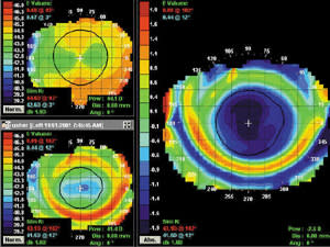
Lenses that have inadequate sagittal height decenter, resulting in a smiley face plot. Figure 4 shows the axial and tangential maps.
The axial map shows that the TxZ is decentred superiorly. Note the red smiley face impinging on the inferior pupil zone. The over-refraction will provide some degree of myopic reduction, but an increase in with-the-rule astigmatism. There will also be flare and halos at night.
The tangential difference map shows the degree of decentration. In the example above, the lens has decentred by approximately 1.0mm.
This is an invalid outcome from an overnight trial. The topography makes the diagnosis, thereby making the refractive outcome redundant.
Correct smiley faces by:
- Recalculating the lens using an extra 8.0 microns in sagittal height or 0.05 eccentricity
- Steepening the reverse curve
- Steepening the alignment curve
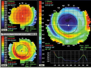
Frowny Faces Frowny faces occur only when the alignment curve is too steep or tight (Figure 5). This results from underestimating the eccentricity, which produces a tight alignment curve or tangent. The lens is therefore slightly too steep. Correct this lens by flattening the alignment curve(s).
Note that the "red ring" is decentred inferiorly, causing ghosting and flare from the superior pupil zone.
Lateral Decentration A lens diameter that is effectively too small, or a cornea that flattens much faster on the nasal side compared to the temporal side, causes lateral decentration. Correct the problem by increasing lens diameter. (Figure 6).
|
|
|
| Figure 5. Frowny face pattern from a lens that is marginally too tight in the alignment curve. | Figure 6. Lateral decentration from a lens that is too small in diameter. |
Central Island Pattern
A central island pattern is a small 1.0mm to 3.0mm central zone of corneal steepening. This results from overestimating the corneal sagittal height or underestimating the eccentricity, which produces a lens with excessive central apical clearance or "bridging" across the central cornea.
Again, overestimated sagittal height is due to an error or failure of the initial topography to appropriately calculate the true elevation of the cornea. The effect this has on the lens tear layer profile was shown in Part I.
There are two main types of central islands. If the initial island is slightly flatter (0.50D) than the original cornea, but still steeper than the surrounding area, it will usually disappear during the first week of wear and could simply be an area of tissue "resistant to change."
|
|
|
|
Figure 7. Corneal map of a central
island. |
The second type of central island (Figure 7) will not resolve with time because the lens fit is too tight, and needs to be altered.
Note that the lens centration is perfect, with the small steep island surrounded by a "moat" of corneal flattening followed by the red ring. The end-point of the refraction is not clear cut, and the BCVA is usually two lines less than normal. This is again an invalid outcome from a trial wear, and the topography's diagnosis makes the refractive information redundant.
Correct a central island by:
- Decreasing the initial corneal sagittal height by 8.0 microns and recalculating the lens. Alternatively, increase the eccentricity value by 0.05.
- Flattening the reverse curve
- Flattening the alignment curve(s)
There are many fine gradations among the examples shown above, but the underlying concept is that the post-wear topography map supplies the diagnosis of the problem. At the start of this article I stated that you should perform the topography prior to the refraction. This is because a refraction that results from a smiley face, lateral decentration or central island provides no relevant clinical data. The topography results make the diagnosis. In the case of a centered treatment area, the refractive change and the subtractive map apical power change should be in close agreement, thereby reinforcing the conclusion of a true bull's-eye plot and an optimal outcome. Mapping the cornea first is a real time saver.
Summary
The modern renaissance of orthokeratology has been dramatically influenced by the introduction of:
- New reverse geometry lens designs, which produce rapid, stable and dramatic alterations in corneal curvature
- Advanced high Dk, GP lens materials for enhanced physiologic response in overnight lens wear
- Advanced corneal mapping techniques that improve accurate first-fit lens selection and post-fitting patient management
- New concepts related to the physiology of fluid dynamics and tissue displacement, which provide a clearer understanding of how orthokeratology works.
The advantages of CCT over traditional keratometry for orthokeratology are enormous. The ability to visually monitor corneal changes on a level measured in microns is critical to the success of the procedure. This is especially true for better understanding and resolving problems that arise in the post-fitting follow-up. Just as the slit lamp is an essential requirement in our practices today, practitioners should now consider CCT the "gold standard" of care for use with modern orthokeratology.
Dr. Mountford is an optometrist in private practice specializing in advanced contact lenses for keratoconus, post refractive surgery and pediatric aphakia. He is a visiting contact lens lecturer to QUT and UNSW, Australia.
Dr. Noack is an optometrist with expertise in advanced contact lens mathematic and computer programming. He has recently retired from practice to work fully on computer applications for contact lens design and manufacture.


