ORTHOKERATOLOGY
Orthokeratology for Hyperopia and Presbyopia
Learn what modifications are needed to design orthokeratology lenses for hyperopia and presbyopia.
By Bruce T. Williams, OD, FIAO
Orthokeratology uses the forces created under specially designed GP lenses, or molds, to temporarily change corneal shape. While orthokeratology usually brings to mind myopia corrections and myopia control, ortho-k lenses can be designed to visually correct hyperopia and presbyopia as well. This article will discuss the mechanisms behind ortho-k and will provide techniques for achieving corrections for hyperopia and presbyopia.
Initial Considerations
When initiating orthokeratology for hyperopia or presbyopia, a number of considerations need to be addressed with respect to how the image will be cast upon the retina. Unlike conventional orthokeratology for myopia, steepening the central cornea pulls the resultant foci forward. This, in itself, is not the concern. Because the central cornea steepens not as a sphere but as an aspheric surface, the subsequent shape significantly increases the corneal higher-order aberrations (Hiraoka et al, 2005). Particularly affected is spherical aberration. Paracentral compression, as opposed to central suction force, seems to be the primary mechanism in hyperopic orthokeratology (Gifford et al, 2009). Thus, when viewing a topographical elevation map, the central cornea will not appear elevated, but the paracentral area will show significant flattening on the tangential map (Figure 1).
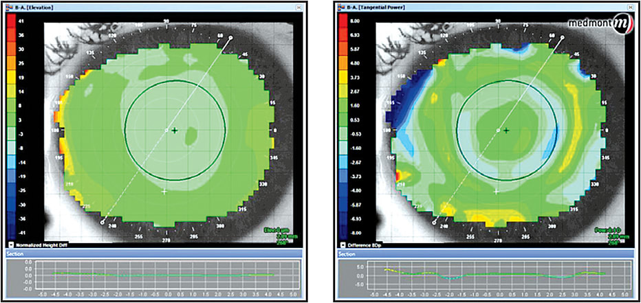
Figure 1. An elevation map (left) and tangential map (right).
When the treatment is initially completed, patients will usually complain of significant glare and halos. After a given amount of time that varies from patient to patient, the symptoms will subside, and visual function will return to a more normal perception. This may be due to some brain adaptation, or the emmetropization that is effective during development may also be effective with acquired variations in corneal shape. Although myopic laser-assisted in situ keratomileusis (LASIK) induces significant corneal aberrations, the level of partial compensation of corneal aberrations by internal structures remained unchanged (Gatinel et al, 2010).
Histology
Much controversy surrounds the histology of what is really happening when orthokeratology affects the resultant refraction. Alharbi and Swarbrick (2003) determined that the majority of the refractive error change was due to corneal epithelial cell migration. Choo et al (2008) found that the epithelium plays a major role in the changes induced by the orthokeratology procedure. This study suggests that both the wearing time and the posterior design of the contact lens dramatically influences the shape and thickness of the epithelium.
Efforts are being made to try to explain the forces in play with orthokeratology for hyperopia and how the epithelium changes to induce the refractive changes (Figure 2). These forces, whether mechanical or fluid in nature, do appear to change the thickness of the epithelium (Figure 3). The underlying question remains as to whether the epithelial change is sufficient to produce the actual refractive change seen.
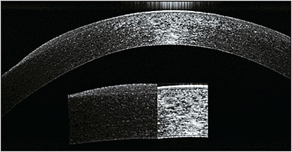
Figure 2. Comparison of central versus midperipheral epithelial thickness after orthokeratology.
COURTESY OF LACHLAN SCOTT-HOY
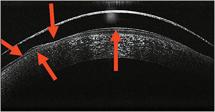
Figure 3. Vector forces during hyperopic orthokeratology.
COURTESY OF LACHLAN SCOTT-HOY AND CHARL LAAS
Reinstein et al (2009) reported a case study of a –3.25D myope in which the epithelial thickness profile was altered, with up to 18 microns of central epithelial thinning and up to 16 microns of annular midperipheral epithelial thickening. There also appeared to be a degree of stromal changes, with central stromal thickening and midperipheral stromal thinning, particularly in the left eye. The conclusion was that “refractive changes during orthokeratology treatment are mainly induced by changes in epithelial thickness profile, while stromal changes may also contribute to a small extent.” Intuitively, we may conclude from this that with central stromal thickening and midperipheral thinning, the stroma may tend to protrude in the midperiphery as it does in keratoconic thinning and actually enhance the orthokeratology effect. This is strictly speculation, and if it pertains to hyperopic orthokeratology, it would certainly need to be studied.
Some researchers have studied the role of the epithelium with instruments such as a two-headed ultrasound pachymeter and found little or no change in epithelial thickness after orthokeratology, thereby suggesting that the major contributor to refractive change lies within the stroma (Weitkamp et al, 2008). With epithelial debridement and corneal cross-linking after orthokeratology, the effect lasted longer compared to with discontinuation of standard lens wear; this also suggests that the stroma is, at least, partially involved in the refractive changes (El Hage and Seiler, 2011).
Mechanism—The Forces in Play
To understand how hyperopic/presbyopic orthokeratology actually changes the shape of the cornea to produce the desired refractive effect, we should consider the forces acting under the molds. Let’s first consider the forces acting on the contact lens mold itself as it relates to the corneal surface. The forces acting on a contact lens are gravity, lid force, surface tension, and tear layer (fluid) forces (Mountford et al, 2004; Hayashi and Fatt, 1980). For the purpose of this discussion, we will not consider the force of gravity as a significant factor in hyperopic corneal molding.
We know that lid force, in itself, is not sufficient to cause corneal shape change; but, lid force becomes a significant factor in closed-eye orthokeratology, both in lens stabilization and in maintaining even surface pressure on the molds. Surface tension exists around the edge of the lenses. Although this is a major factor in the open eye, as pointed out by Alharbi and Swarbrick (2003), surface tension requires a fluid/air interface. Such an interface does not exist in the closed-eye environment of overnight orthokeratology. This would lead us to believe that surface tension, again, is not a major contributor to the effects of corneal molding.
This leaves us with tear layer (fluid) forces, also described as “squeeze film forces” when applied to corneal molding. The present nonlinear expressions have been compared with existing models for short cylindrical squeeze films showing that the force terms are either exactly the same or have the same trends with instantaneous eccentricity values (Han and Rogers, 2001). Applying these findings to orthokeratology, we can presume, for all practical purposes, that the substance of our investigations should center on the tear layer profile.
A tear film with a peripheral film thickness of one-half of the central film thickness produces more than three times the squeeze force as that produced by a constant tear film thickness with the same central clearance (Allaire and Flack, 1980). This would help explain the midperipheral compression and central steepening exhibited with certain orthokeratology lens designs for hyperopia. This could be very loosely described as central “sucking” and midperipheral “compression” forces as shown in Figure 3. Fluids, as most things in nature, are always seeking some form of equilibrium. When a hyperopic mold is placed on the cornea, the pressure gradients that occur beneath will seek that equilibrium. Fluids are incompressible, so to find equilibrium, the moldable tissues beneath the lens will be forced to change shape or position to accomplish this. Hence, the topographical changes that we see on the cornea.
The Importance of Corneal Topography
For the design and management of hyperopic orthokeratology, a corneal topographer is an essential piece of equipment. It helps in designing an ideal lens for a specific cornea and refraction. It also helps in monitoring the effects of our designs. A topographer can show us how and when to troubleshoot a particular design. The topographical maps that are most useful in hyperopic orthokeratology are the tangential, axial, elevation, and subtractive (difference) maps.
If light is reflected from an oblique point on a curved surface, two points of focus will be apparent: the tangential and the sagittal points. The tangential radius represents the true curve or shape of the cornea, as it represents the area of the cornea that contains the target mires. It is presented as the radius of the corneal surface perpendicular to the reflected mires.
The fixation point is very important when taking any topographic map, and it should be adjusted to the geometric center of the cornea rather than to the line of sight, usually fixating one to three rings nasal to the central fixation target. With this method, we can obtain a better understanding of the true position of the treatment areas of the cornea (Figure 4).
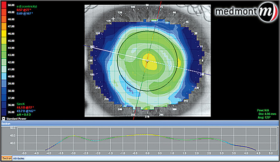
Figure 4. Tangential map post-hyperopic orthokeratology.
Axial maps are useful in determining the effect of the treatment on the optical qualities of the cornea. This is more related to the actual refractive change (Figure 5).
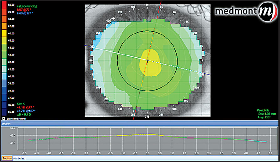
Figure 5. Axial map post-hyperopic orthokeratology.
Elevation maps can give us an idea of the relative differences found on the corneal surface with respect to a reference sphere. They are very useful when evaluating the corneal irregularities that are referenced from that sphere. Elevation maps can help when deciding whether to use a toric or a freeform mold design. Some manufacturers suggest using the elevation maps to help determine the best fit for their dual axis lens. This helps with the alignment of the landing zone to produce a 360° “so called” seal in the peripheral cornea to aid in capturing the full effect of the squeeze film forces under the mold. Elevation maps calculate these differences in microns; as many software programs design lenses relative to clearance, they can be instrumental in determining the peripheral values (Figure 6).
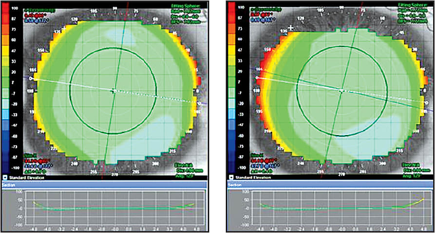
Figure 6. Elevation map pre- and post-hyperopic orthokeratology. Note that even though the tangential difference map below indicates 1.2D of curvature change, the elevation maps are strikingly similar.
Difference or subtractive maps not only show the point-by-point difference in radius of the pre- and post-plots, they are also important in describing the areas of greatest change, thus the position of the mold in the closed-eye environment. Many of the modifications needed to improve the fit, if necessary, can be deduced from the appearance of the difference map (Figure 7).
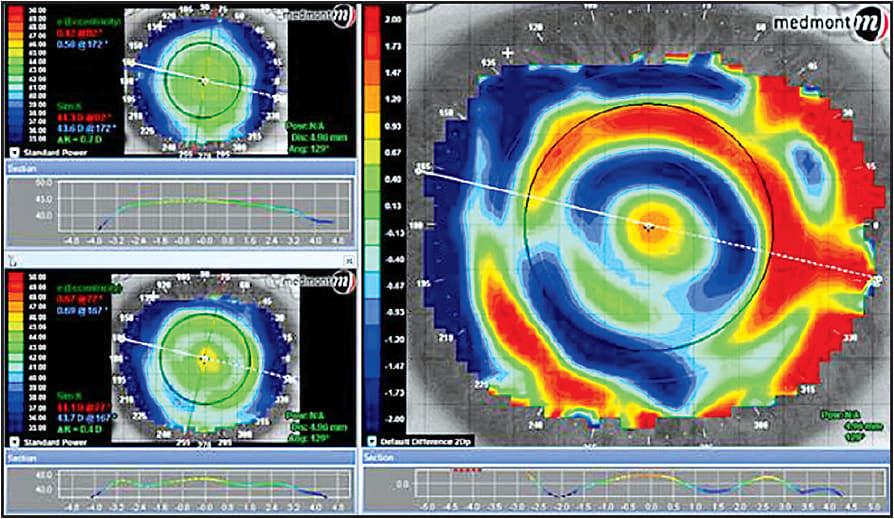
Figure 7. Difference map with the upper left sagittal pre-treatment map and lower left sagittal post-treatment map. The map on the right shows the point-by-point difference in radius between the pre- and post-treatment maps.
Lens Design Philosophies
There are two basic design philosophies, both with many variants. One uses a continuous aspheric curve that is varied to produce a mold that is significantly steeper in the central treatment zone and is designed to apply pressure to the paracentral cornea (Figure 8). Continuous aspheric designs are, like all orthokeratology lenses, fit on sag philosophy. To properly understand how these lenses work on the cornea, we must first understand the shape of the surface that we intend to mold. We know that the vast majority of human corneas are prolate and that the average eccentricity is 0.50. Approximately 95% of corneas have eccentricities (e-values) in the range of 0.30 to 0.70 (Guillon et al, 1986). Corneal descriptors can be defined in terms of eccentricity (e), shape factor (p) or asphericity (Q). These descriptors are all related via the formulas: p = (1 – e2) and (Q = –e2). Q has the advantage of being able to describe either a prolate (positive Q-value) or an oblate (negative Q-value) surface. The relationship between the asphericity of the cornea and the back surface of the lens will be discussed in the section on tear layer thickness (TLT).
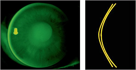
Figure 8. Continuous aspheric edge to edge yields a larger treatment zone that gradually steepens the central cornea into a more aspheric shape. The corneal eccentricity increases as the lens is worn, creating a natural multifocal effect on the central cornea. The outer zones are also aspheric and work to apply peripheral pressure, which helps with the central steepening.
COURTESY OF STEVE ERNST
The other, more common design is a reverse geometry lens that again produces a steeper central treatment zone and uses the area juxtaposed to the beginning of the reverse curve to apply inward pressure to the paracentral treatment zone. The paracentral flattening advertently causes a steepening of the central treatment zone to produce the intended hyperopic correction.
One design uses a system of curves that are necessary to complete hyperopic treatment. In this design, the back optic zone radius must be shorter than the corneal radius. The sigmoid connecting geometry is initially convex to create a “knee” that compresses the paracentral cornea. The concave sigmoid connecting geometry returns the lens to the peripheral cornea, and the tangential landing zone aligns with the peripheral cornea to create the necessary closure of the hydrodynamic fluid force system (Figures 9 and 10).
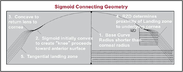
Figure 9. Proximity control for hyperopic orthokeratology.
COURTESY OF KEN KOPP
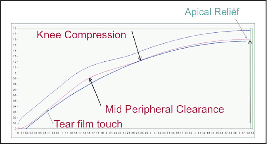
Figure 10. The landing zone is comprised of a plano flap that can only be tangent to any curved surface. The sagittal depth is controlled by the variance of the reverse zone depth by varying the length of the sigmoid curve.
COURTESY OF KEN KOPP
Dr. Hsiao-Ching Tung describes his hyperopic (H) orthokeratology lens as having a steep-flat-steep-flat design (Tung, 2004). The dual geometric design has a steep central aspheric curve that blends into a very flat paracentral (plateau) zone, which acts to compress the paracentral cornea toward the center to enhance the central steepening. This is surrounded by the reverse curve for a tear pool that connects to the peripheral aspheric curves for alignment and centering (Figure 11).
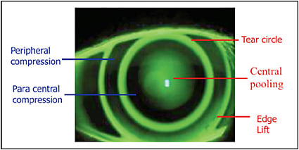
Figure 11. A hyperopic orthokeratology lens with a steep-flat-steep-flat design.
The Impact of Tear Layer Thickness
When looking at any orthokeratologic treatment, whether it be for myopia, astigmatism, hyperopia, or presbyopia, the influence of the tear film squeeze forces are paramount to the discussion of how it works. A computer model of the calculated clearance between the posterior lens surface and the anterior corneal surface generates all of the data that we use to look at the tear film. It would be helpful to have a way of accurately measuring the tear film thickness (TFT) and applying formulas to calculate the actual forces in play at any given axis that mold the cornea.
Optical coherence tomography (OCT) is an optical signal acquisition and processing method that can be considered an interferometric technique. OCT was first used to assess tear film by Wang et al (2006), who reported values of approximately 3µm. Using this technique or others such as fluctuation analysis by spatial image correlation (FASIC) (Azartash et al, 2011), a program could be developed to utilize the predicted TLT from the topography and clearance analysis to design a lens to maximize the forces necessary to accomplish the desired orthokeratology effect.
Some computer-assisted design programs utilize tear layer clearance to construct a lens with the predicted curves necessary to induce the proper changes in corneal topography. Figures 12 and 13 show two examples. Tools such as these are very useful in describing the initial lens. Due to the dependency of the design on the model of the cornea that is constructed based on the algorithms used by the designers of the individual instruments, specific intricacies vary greatly between designs.
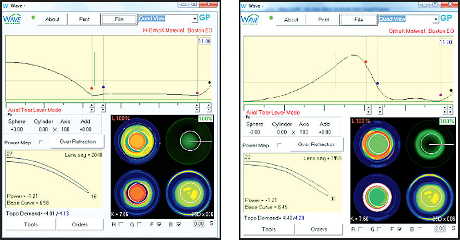
Figure 12. Comparison of tear layer thickness in hyperopic versus myopic orthokeratology.
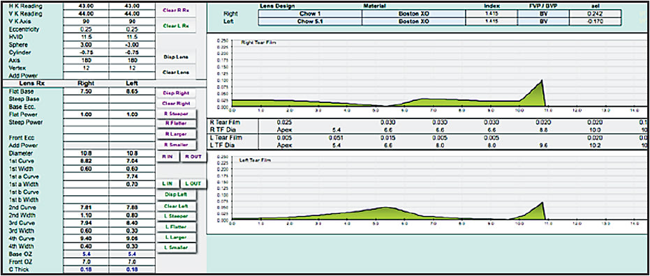
Figure 13. Comparison of tear layer thickness in hyperopic versus myopic orthokeratology.
The primary goal of these programs that import the topography data is to define the shape of the cornea in as many meridians as possible so an ideal posterior surface can be designed on the mold to maximize the therapeutic effect. These programs use specific algorithms to extrapolate the shape of the peripheral cornea. Because corneal peripheries vary greatly among individuals, the projected design may not be as ideal as we would like. Many protocols include a “fitting set” for the purpose of refining the initial mold parameters.
From our discussion on corneal shape and eccentricity (e), shape factor (p), and asphericity (Q), we must realize that not all meridians of the cornea have the same e-value or rate of change. Most corneal topographers and automated keratometers will provide the average value of all meridians, although some will give e-values per meridian or quadrant. Instrument manufacturers do not disclose from what location they produce these measurements, how far from center, and how much is extrapolated. This makes it impossible to use these values interchangeably between instruments. Some instruments will provide values in the primary meridians, which is a little more information but not sufficient to design an entire posterior surface with absolute accuracy.
Because the corneal shape cannot be defined as a standard ellipse, the need for understanding the shape becomes clinically significant when designing orthokeratology molds. There is a low, but clinically significant, correlation between refractive error and eccentricity (higher hyperopia = increased eccentricity). Average values are incorporated by designers to produce trial sets as a means of facilitating lens fitting in a clinical setting. This is where it becomes important to employ your skill in understanding fluorescein patterns, including central pooling, paracentral compression, reverse curve, peripheral alignment, and edge lift (Figure 14).
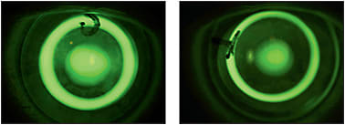
Figure 14. Different appearance of sodium fluorescein pattern with change of trial lens parameters.
Excessive sagittal height at the apex may cause bubbles to form, or it may cause what is known as a “central lake.” A central lake results when the apex of the treatment zone shows a flattening at the peak. Too little sagittal height will inhibit steepening, and the treatment will not achieve the desired correction.
Paracentral compression is important in forcing pressure toward the center to allow for maximum central steepening. The reverse curve maintains the fluid balance, and the alignment curve is important to close the system and align the lens on the cornea. If any one of these parameters is miscalculated, the treatment will be somewhat less than optimal.
General Rules for Fitting Orthokeratology to Correct Hyperopia and Presbyopia
The first step in any fitting process is to know as much about the cornea as you can. Whether your fitting philosophy is empirical, by trial lens, or computer-assisted, you will need to have a feeling for the overall curvatures and shapes that you are dealing with. Some type of topography makes it much easier to design a lens that will be successful the first time. Some designs start with central keratometry readings and refraction and are designed by the laboratory. These work best on lower amounts of hyperopia and may require at least one remake to alter certain parameters to enhance the fit.
If you are using a trial lens system, most manufacturers have a suggested first trial lens that is determined from the steep and flat K readings. Some use the flat K and some use the mean K. Be sure to include the Jessen Factor, which is an amount of over-correction sought to achieve full correction, in the final determination of the base curve; they vary from +0.50D to as high as +2.00D. This also allows for any regression that may occur during the day.
Any fitting that uses a trial lens set must be refined by fluorescein observation. If it is a completely aspheric design, look for central pooling and an even distribution of peripheral alignment, with a little heavier touch in the paracentral area from 1mm to 3mm away from center (Figure 8). When using a reverse geometry trial lens, the ideal pattern is central pooling, heavy touch paracentrally, a bright reverse curve, peripheral alignment, and a bright edge lift (Figure 14). Centration is critical for any design. The better the centration, the less aberration and distortion in the final treatment.
Corneal diameter is also very important when designing hyperopic ortho-k lenses. Flatter corneas generally require a larger diameter. Some fitting sets consider this, while others include just one average lens diameter. Generally speaking, the ideal diameter will cover from 93% to 97% of the cornea measured from the horizontal visible iris diameter (HVID). It may be valuable to measure the vertical visible iris diameter (VVID) as well. This is especially important when fitting toric peripheral curves for better 360° closure of the tear film system.
These same general rules apply when using a computer-assisted program to design the lenses. Computer-assisted programs have a simulated fluorescein pattern that allows designers to visualize the pattern as it should appear on the cornea with the final lens. Other programs will prompt you to enter the e-value to aid in constructing the peripheral alignment curve.
Hyperopic/presbyopic orthokeratology designs have an extra central steep curve in center-near lenses or a steeper curve in the extreme paracentral area, central to the reverse curve, in a center-distance lens. They may also simply use a smaller treatment zone to incorporate the reverse curve steepening to enhance the near add.
Computer-assisted design programs have built-in nomograms that try to predict the peripheral corneal slope from the data collected by the topographers’ 9mm to 9.5mm coverage plot. Some topographers have a composite function that can be used to acquire more data in the peripheral cornea that can be uploaded into the design program to enhance the amount of data available to be analyzed.
Some general fitting pearls would include the following:
1) If trying to correct more than +3.00D of hyperopia, it is more effective to use a multifocal center-near design.
2) Centration is a key factor and is controlled by the same principles as any rigid lens.
Conclusion
Regardless of whichever philosophy you are using, it is important to consult with the manufacturers and distributors to glean as much information as possible to streamline the fitting process and give patients the ultimate treatment experience. CLS
For references, please visit www.clspectrum.com/references and click on document #249.

| Dr. Williams is in private practice in Seattle. He is a member of the American Optometric Association, Washington Optometric Physicians, British Contact Lens Association, International Association of Contact Lens Educators, and a Fellow of the International Academy of Orthokeratology. He serves on the Board of The American Academy of Orthokeratology and Myopia Control where he is chairman of the Education Committee. He is an Advisory Board Member of the GPLI and a reviewer for Contact Lens and Anterior Eye, the journal of the BCLA. |


