Your patient is scheduled for an appointment today for what you hope is the last contact lens follow-up visit of a months-long fitting process. Multiple modifications have been made to the scleral lens fit and prescription with the hope that the lens provides the best visual acuity for the patient and is comfortable to wear throughout the day. The patient states that—while the comfort of the lenses is great—he is not happy with the vision; however, he is unable to elaborate or to describe why.
The patient’s visual acuity is 20/20, measured using a high-contrast visual acuity chart, and your over-refraction is plano. The patient may be suffering from uncorrected higher-order aberrations. But, without an instrument to verify this hypothesis or optical lenses to correct these aberrations, you explain to the patient that there are no other treatment options available at this point. The patient leaves feeling unsatisfied because of his inability to see the world clearly.
OCULAR ABERRATIONS
Ocular aberrations are caused when light that enters the eye speeds up or slows down as a result of small imperfections in the anterior or posterior surfaces of the cornea or crystalline lens or as a result of myopia or hyperopia. Uncorrected aberrations can leave patients unsatisfied with their quality of vision. Wavefronts can be used to describe how light emerges from a source. In a perfect optical system, a wavefront is refracted by the cornea and focuses perfectly on the retina, creating a clear image. However, imperfections in the cornea or crystalline lens prevent the wavefront from achieving a sharp focus, causing blurry or distorted vision.
The difference between the ideal wavefront and the actual wavefront of a given eye is known as wavefront error. Wavefront error is most commonly represented using a Zernike polynomial, which is a mathematical equation that describes the fit of the wavefront profile.1
Zernike polynomials can be categorized using either a single-index (CN) or a double-index
(

)
system and are displayed in a tree or pyramid-like fashion. An example of a Zernike polynomial tree displaying up to the 10th radial order has been described by Lakshminarayanan and Fleck.2 Aberrations located near the center will typically have a more significant impact on quality of vision compared to aberrations located near the edges of the tree.1
Using the single-index system, piston, which is located at the top of the Zernike polynomial tree, is labeled as n = 0. Each subsequent Zernike polynomial is labeled as 1, 2, 3, etc. (e.g., defocus = C4, spherical aberration = C12). In the double-index system, M = angular frequency (orientation) sine (–) and cosine (+), N = radial order, and C = coefficient (magnitude). First- and second-order (N = 1 to 2) polynomials are commonly referred to as lower-order aberrations, while higher-order aberrations (HOAs) are represented by third-order and above polynomials (N = 3+).
Zero and first radial order are commonly referred to as piston and as tip/tilt, respectively. Piston and tip/tilt are generally ignored when analyzing a wavefront error profile, as piston adds a constant that does not affect image quality, and tip/tilt merely changes the positioning of the image but does not induce image degradation. Lower-order aberrations comprise 85% to 90% of total ocular aberrations in a myopic population and are represented by defocus and astigmatism.3 Defocus is most closely associated with spherical refractive error and can be optically neutralized—as can astigmatism—using spectacles and standard contact lenses. Conventional scleral lenses correct defocus and astigmatism, and the tear layer may also correct up to approximately 65% of HOAs.4,5
Aberrations in a normal population were measured by Porter et al in 109 normal subjects who had spherical refractive error between +6.00D and –12.00D and astigmatic refractive error less than –3.00D using a Shack-Hartmann wavefront aberrometer at a 5.7mm pupil diameter.3 Defocus accounted for 80% of the total aberration profile and was the largest in magnitude, followed by astigmatism. Together, the lower-order aberrations (defocus + astigmatism) accounted for 92% of the total variance of aberrations. Spherical aberration was the largest HOA in the cohort, with an average of +0.138µm ± 0.103µm. The means of all other HOAs were approximately zero. Although spherical aberration and defocus are both located toward the center of the Zernike polynomial tree, the two terms are quite different and should not be confused. The magnitude of defocus is highly correlated with axial length, whereas spherical aberration is dependent on the anterior and posterior curvature of the cornea and crystalline lens.6
Spherical aberration is caused by light at the edge of a lens or cornea refracting at a shorter or longer distance compared to light centrally. As a quick review, contact lenses may induce spherical aberration as a result of their curved surface (negative powers induce negative spherical aberration, positive powers induce positive spherical aberration), but the magnitude and orientation may vary among lens designs and manufacturers. In an ideal optical system, patients would be fit with a contact lens that induces negative spherical aberration to negate the spherical aberration from the lens itself as well as from the eye’s natural and inherent positive spherical aberration. Aspheric contact lenses were designed to accomplish this goal, but they can fall short when patients have higher- or lower-than-average spherical aberration or when the contact lens overcorrects, which may result in negative spherical aberration.
Multiple Zernike modes are required to describe a specific wavefront for an optical system, which can present challenges during analysis. As a result, single-value metrics exist to describe the magnitude of wavefront aberrations as one single number. Root mean square (RMS) is a commonly used metric to describe the magnitude of wavefront aberrations in an optical system. To analyze the specific impact that HOAs have on an optical system, higher-order RMS (HO RMS) can be utilized. HO RMS is equal to the square root of the squares of Zernike coefficients:

HO RMS increases as the pupil diameter enlarges, and it also increases with age.7 This relationship partially explains why individuals have more difficulty functioning in a dimly lit environment in which their pupil would be more dilated than in a brightly lit environment. While HO RMS indicates the magnitude and specific aberrations in an optical system, it fails to describe how the aberrations interact to improve or reduce an individual’s quality of vision.1 For example, two individuals may have a HO RMS of 1µm, but this may falsely imply that the vision of the two patients is equal. The abberrations of the first individual may interact in a way that improves his or her visual acuity, while those of the second individual may interact in a manner that degrades visual acuity. Although the HO RMS value is the same for both patients, the outcomes are significantly different because of the varied interaction between the aberrations.
Visual Strehl ratio (VSX) is another single-value metric that will help with understanding the visual outcomes.8 Unlike RMS, VSX includes a measure of neural processing by the visual system and ranges from 0 to 1, in which 1 is the best visual image quality possible and 0 is the worst.
HOW ABERROMETERS WORK
Wavefront aberrometers are key to better understanding a patient’s visual optical system. Fortunately, aberrometers are becoming more widely available in the commercial market. As with many newer instruments, manufacturers are designing aberrometers in combination with other diagnostic instruments, which may be more affordable to a practitioner compared with a stand-alone unit. If your clinic does not have a wavefront aberrometer, consider referring to a local eyecare practitioner for a wavefront aberration scan when a patient still has visual complaints or if you suspect that he or she may have residual HOAs.
There are several types of wavefront sensors: Shack-Hartmann, ray-tracing, and pyramidal, which are all considered to be whole-eye wavefront aberrometers. Although the technological differences between the wavefront sensors is beyond the scope of this discussion, clinicians should understand key differences between whole-eye wavefront sensors, mentioned above, and instruments that measure only the aberrations of the cornea (e.g., corneal topographers and tomographers). Although corneal topographers and tomographers provide detailed information about the wavefront aberrations originating from the anterior and—in some instruments—from the posterior surface of the cornea, they neglect to measure the aberration profile of the anterior and posterior surfaces of the crystalline lens as well as the eye’s axial length.
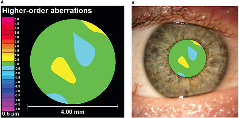
Wavefront aberrations are displayed in a wavefront map (Figure 1A). A wavefront map may appear similar to a corneal topography map at first glance, but it contains several key differences. First, wavefront aberrations are measured within a patient’s pupil (Figure 1B), as compared to a corneal topography, which is measured across the entire corneal surface. Second, the wavefront aberration map colors represent the magnitude of aberration rather than curvature, as measured by a corneal topographer. Warm colors (e.g., yellows, reds, oranges) indicate that the wavefront is advanced or in front of the optimal reference surface. Cool colors (e.g., blues, purples) indicate that the wavefront is slowed or behind the optimal refracting surface. These colors should not be confused with the colors representing steep or flat curvature values from a corneal topographer. A perfect optical system—i.e., zero aberrations—would have a solid green wavefront error map, but this is not feasible in the human eye. Figure 1A shows an eye that has low levels of HOAs.

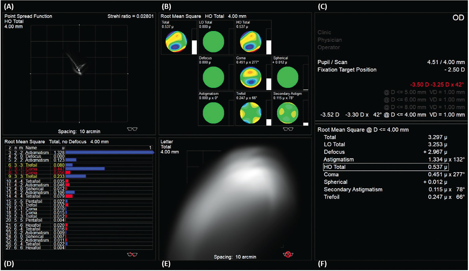
Because wavefront aberrations change depending on a patient’s pupil size, it is important to analyze wavefront aberration measurements using the same pupil size for a particular patient. In other words, you cannot simply compare the HOA profiles for a patient when one has a pupil of 4mm and the other is at 6mm. To help with this comparison, all wavefront aberration maps should display the pupil size at which the measurement was taken. A table of normative HO RMS values, such as Table 5 from Applegate et al,7 can be used to determine whether a patient’s HO RMS falls below or above the average range based upon his or her age and pupil diameter. Although different instruments may vary, Figure 2 illustrates data displayed in one wavefront aberrometer’s software. Aberrometers will also output a Seidel refraction for the optical system imaged (Figure 2C). This refraction is often utilized to refine the spherical and cylindrical components of a conventional scleral lens with the phoropter.

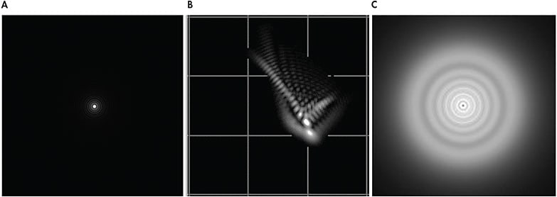
Data from wavefront maps can be used to create a point spread function (PSF) (Figures 2A and 3B). PSFs are pictorial representations of how a pinpoint light source would appear in an aberrated system. Additionally, this data can be utilized to create a simulated retinal image of a letter chart (Figures 2E and 3C). These simulated images provide eyecare practitioners with real-life examples of how the wavefront aberrations might alter a patient’s retinal image. It should be noted that simulated retinal charts are built using objective data and do not consider the neural processing from the human visual system.

OCULAR CONDITIONS AND HIGHER-ORDER ABERRATIONS
HOAs may be caused by any irregularity in the anterior or posterior surface of the cornea or crystalline lens and can result in some of the most visually significant distortions. Common conditions that may result in elevated levels of HOAs include corneal ectasias such as keratoconus and pellucid marginal degeneration, corneal transplants, and post-refractive surgery procedures such as radial keratotomy (RK).
Although the composition of each patient’s wavefront profile is unique, there are several Zernike modes that may be more prominent in specific conditions. Keratoconus typically produces a central-to-inferior corneal steepening. The size and location of the cone may significantly influence the resultant aberration pattern. When the patient has a centrally located cone, spherical aberration tends to be the primary source of HOAs.10 If the cone location shifts inferiorly, the patient will most likely exhibit elevated levels of negative vertical coma, spherical aberration, and trefoil.11,12 Similarly, vertical coma tends to be more pronounced as a result of inferior steepening from pellucid marginal degeneration. Patients who have elevated levels of coma may notice a comet-shaped tail radiating around lights and images (Figure 4B). Although there are many commercial aberrometers available, all display very similar data, as observed in an individual who has keratoconus measured using three different wavefront aberrometers (Figure 5).


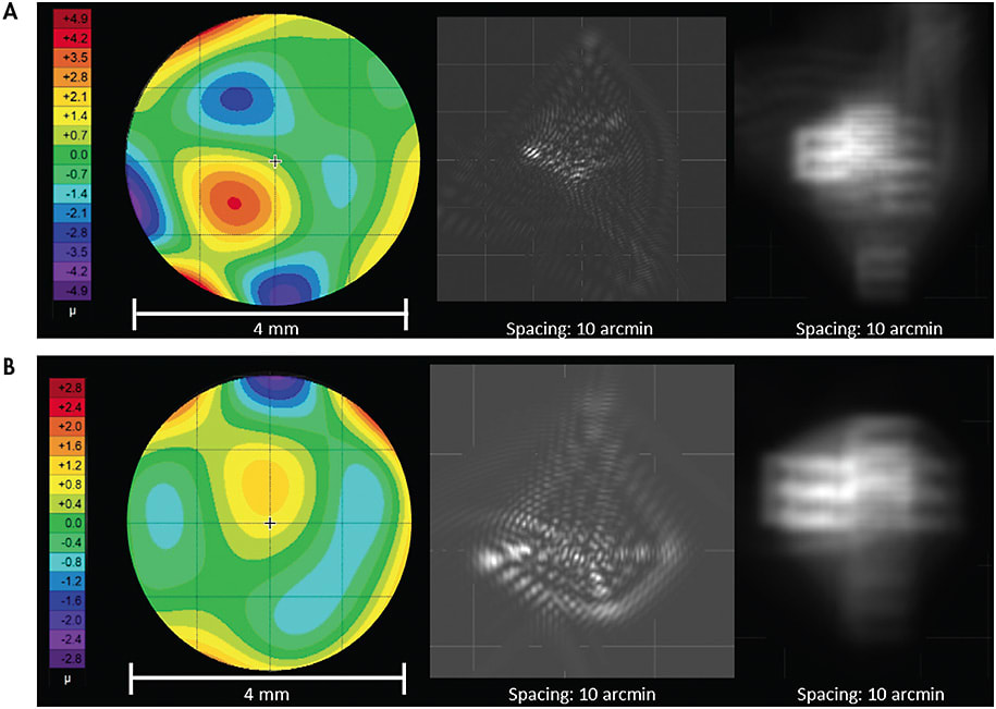
As corneal transplants can result in a wide variety of topographical shapes, their wavefront aberration profiles can vary as well. HOAs that may be prominent following corneal transplantation include spherical aberration, trefoil, secondary astigmatism, and tetrafoil,13 as observed in the patient in Figure 6A who underwent a corneal transplant following radial keratotomy (RK) surgery. Elevated HOA levels may also be present in post-refractive-surgery corneas such as RK. Third- and fourth-order aberrations tend to be more abundant in these post-refractive-surgery corneas (Figure 6B).13,14

WAVEFRONT-GUIDED LENSES IN A RESEARCH ENVIRONMENT
The concept of correcting HOAs is not new. Soft contact lenses were first investigated as devices in which wavefront-guided optics were added. Sabesan et al15 and Marsack et al16 are two examples of research teams that demonstrated improvement in high-contrast visual acuity in keratoconic eyes using soft wavefront-guided contact lenses. As you can imagine, a wavefront-guided optical device must be rotationally and translationally stable to provide the optimal improvement in visual acuity and image quality; otherwise, the optical device may induce more visually significant aberrations. As a result, soft contact lenses at that time did not have the stability required for optimal delivery of wavefront-guided optics.
Scleral lenses provide the stability required for wavefront-guided optics. The feasibility of incorporating wavefront-guided optics into scleral lenses was demonstrated successfully by several research teams.4,5,17 More recently, Hastings et al5 compared optical and visual performance of eyes wearing conventional scleral lens corrections and wavefront-guided scleral lens corrections. Mean HO RMS was reduced 43% from conventional scleral lenses to wavefront-guided lenses.5 This success further demonstrated that technology can accurately measure, design, and manufacturer wavefront-guided scleral lenses in a manner that can improve a patient’s visual acuity and image quality.
FITTING WAVEFRONT-GUIDED LENSES IN A CLINIC ENVIRONMENT
Today, it is exciting to see wavefront technology and HOAs being discussed more frequently at educational conferences. Wavefront-guided scleral lens designs, for which commercial manufacturers have the capacity to streamline the overall process of measuring, designing, and fitting wavefront-guided scleral lenses for clinicians, are beginning to emerge in the commercial market. While it is typical for clinicians and investigators in a research environment to spend more time with each patient, it may be detrimental and even costly for clinicians working in a non-research, clinic environment to do so. To improve outcomes and success, clinicians fitting wavefront-guided scleral lenses must have a basic understanding of wavefront aberrations and how these devices differ compared to conventional scleral lenses.
Often, it can be challenging to identify ideal patients who would benefit from wavefront-guided scleral lenses. The first method to identify ideal candidates does not even require the use of a wavefront aberrometer; simply ask patients about the quality of their vision. Clinicians should ask their patients to describe how they see objects in their environment. Sometimes this detailed information can get lost if a clinician is focused solely on measuring a patient’s high-contrast visual acuity. Nguyen et al18 published an image in which a patient drew a pictorial representation of how he saw multiple car taillights at night rather than a single taillight. The patient’s subjective response provided a clue as to the magnitude and structure of his wavefront aberrations, as accurately depicted in the PSFs.18
Ideal wavefront-guided scleral lens candidates may also be identified by measuring residual aberrations over their conventional contact lenses. Prior to measuring HOAs, clinicians must correct lower-order aberrations. If not, the large magnitude of the lower-order aberrations will outweigh the smaller magnitude of HOAs. An aberrometer can then be used to capture repeated measurements to determine whether patients have elevated levels of residual HOAs. Acquiring repeated measurements, which is common protocol in a research environment, should be performed in a clinic environment as well, as a collection of measurements provides a more accurate representation of a patient’s residual aberrations.
If a patient’s HO RMS is significantly higher compared with the normative values in Applegate et al,7 then the patient may benefit from being fit in a wavefront-guided scleral lens. Because HO RMS is a single-value metric, it is important for clinicians to also analyze which HOAs are present and the relative magnitude of each. Wavefront aberrations, when combined, can lead to an improvement or a worsening of visual performance. For example, Zernike modes that are located two radial orders apart and have the same angular frequency produce less distortion when added together than do each single mode separately (e.g., defocus and spherical aberration).19
With regard to wavefront-guided scleral lens care, you may think at first glance that applying digital pressure when cleaning and disinfecting these lenses will disrupt the optical profile of the wavefront optics. Wilting et al demonstrated that cleaning wavefront-guided scleral lenses 378 times did not significantly change their optical profile or base curve.20 Although this research was performed in vitro, future areas of interest include how the scleral lens wavefront optics and parameters, including base curve, perform in an in vivo environment.
CONCLUSION
As clinicians, it is important that we continually strive to better comprehend our patients’ quality of vision. Talking to patients and understanding how they visualize the world rather than judging their quality of vision based on a single visual acuity number is a first step. A wavefront aberrometer is a tool that can be incorporated into a clinical environment to expand upon these details. Wavefront maps have the ability to quantify the way in which light travels through the eye. They can be used to produce graphics and visualizations such as PSFs and visual acuity letter retinal image simulations that can help clinicians understand their patients’ vision, lead to more accurate diagnoses, and produce better treatment outcomes.
It is exciting to see wavefront-guided scleral lenses start to emerge in the commercial market. Fitting wavefront-guided scleral lenses is more complex compared to fitting conventional scleral lenses, but it can be highly rewarding for patients who otherwise would suffer devastating visual effects of residual HOAs. As our understanding of a patient’s quality of vision expands, so will the technology to more precisely diagnose, measure, and correct ocular aberrations. Start talking to your patients about their quality of vision in addition to measuring their high-contrast visual acuity. Ask them to describe or even to draw how they visualize the world. You might just find that HOAs are the cause of a patient’s visual complaints. CLS
REFERENCES
- Thibos L, Applegate R, Schwiegering J, Webb R. Standards for reporting the optical aberrations of eyes. J Refract Surg. 2002 Sep-Oct;18:S652-S660.
- Lakshminarayanan V, Fleck A. Zernike polynomials: a guide. J Modern Optics. 2011 Apr;58:545-561.
- Porter J, Guirao A, Cox I, Williams D. Monochromatic aberrations of the human eye in a large population. J Opt Soc Am. 2001 Aug;18:1793-1803.
- Sabesan R, Johns L, Tomashevskaya O, Jacobs D, Rosenthal P, Yoon G. Wavefront-guided scleral lens prosthetic device for keratoconus. Optom Vis Sci. 2013 Apr;90:314-323.
- Hastings G, Applegate R, Nguyen L, Kauffman M, Hemmati R, Marsack J. Comparison of Wavefront-guided and Best Conventional Scleral Lenses after Habituation in Eyes with Corneal Ectasia. Optom Vis Sci. 2019 Apr;96:238-247.
- Carroll J. Component and correlation ametropia. Am J Optom Physiol Opt. 1982 Jan;59:28-33.
- Applegate R, Donnelly W, Marsack J, Koenig D. Three-dimensional relationship between high-order root-mean-square wavefront error, pupil diameter, and aging. J Opt Soc Am. 2007 Mar;24:578-587.
- Cheng X, Bradley A, Thibos L. Predicting subjective judgment of best focus with objective image quality metrics. J Vis. 2004 Apr;4:310-321.
- Kauffman M, Nguyen L, Hastings G, Applegate R, Marsack J. Correction of Higher Order Wavefront Aberrations Resulting from Severe Keratoconus Delays Corneal Transplant. Scientific poster presented at the Annual Meeting of the American Academy of Optometry, San Antonio, TX, November 2018.
- Jinabhai A, Radhakrishnan H, O’Donnell C. Higher-Order Aberrations in Keratoconus: A Review. Optometry in Practice. 2009 Jun;10:141-160.
- Nakagawa T, Maeda N, Kosaki R, et al. Higher-order aberrations due to the posterior corneal surface in patients with keratoconus. Invest Ophthalmol Vis Sci. 2009 Jun;50:2660-2665.
- Chen M, Yoon G. Posterior corneal aberrations and their compensation effects on anterior corneal aberrations in keratoconic eyes. Invest Ophthalmol Vis Sci. 2008 Dec;49:5645-5652.
- Koh W, Maeda N, Nakagawa T, et al. Characteristic higher-order aberrations of the anterior and posterior corneal surfaces in 3 corneal transplantation techniques. Am J Ophthalmol. 2012 Feb;153:284-290.
- Hjortdal J, Olsen H, Ehlers N. Prospective randomized study of corneal aberrations 1 year after radial keratotomy or photorefractive keratectomy. J Refract Surg. 2002 Jan-Feb;18:23-29.
- Sabesan R, Jeong T, Carvalho L, Cox I, Williams D, Yoon G. Vision improvement by correcting higher-order aberrations with customized soft contact lenses in keratoconic eyes. Opt Lett. 2007 Apr;32:1000-1002.
- Marsack J, Parker K, Niu Y, Pesudovs K, Applegate R. On-eye performance of custom wavefront-guided soft contact lenses in a habitual soft lens-wearing keratoconic patient. J Refract Surg. 2007 Nov;23:960-964.
- Marsack J, Ravikumar A, Nguyen C, et al. Wavefront-guided scleral lens correction in keratoconus. Optom Vis Sci. 2014 Oct;91:1221-1230.
- Nguyen L, Kauffman M, Hastings G, Applegate R, Marsack J. Case Report: What Are We Doing for Our “20/20 Unhappy” Scleral Lens Patients? Optom Vis Sci. 2020 Sep;97:826-830.
- Applegate R, Marsack J, Ramos R, Sarver E. Interaction between aberrations to improve or reduce visual performance. J Cataract Refract Surg. 2003 Aug;29:1487-1495.
- Wilting S, Hastings G, Nguyen L, et al. Quantifying the Optical and Physical Consequences of Daily Cleaning on Conventional and Wavefront-guided Scleral Lenses. Optom Vis Sci. 2020 Sep;97:754-760.


