

A RULE OF THUMB (ROT) may be defined as “an approximate method for doing something, based on practical experience rather than theory. This usage of the phrase can be traced back to the 17th century and has been associated with various trades where quantities were measured by comparison to the width or length of a thumb.”1
In GP practice, a RoT provides the practitioner with a simple practical guide to assist in making a clinical judgement. In addition, it is very helpful for the student. Two commonly used RoT in GP practice are:
• To choose an initial back optic zone radius (BOZR), go 0.10mm steeper than the flattest K reading.
• A change in back optic zone diameter (BOZD) of 0.5mm requires the BOZR be changed by 0.05mm to maintain the same central fluorescein pattern.
However, both of these RoT are only partially correct.
With the increased accuracy of measurement of corneal curvature and shape, it is now possible to build up more accurate RoT to aid in GP practice. This paper aims to provide practitioners and students with a range of RoT in a manner that improves their accuracy.
INITIAL DISCUSSION
The fit, comfort, and centration of a GP contact lens on the eye are affected by several factors: edge tension forces, edge clearance, edge shape, total diameter, lens thickness, etc.2 However, the most important factor affecting overall fit and centration (and hence comfort and vision) is the tear film squeeze pressure (TFSP). This is the pressure that develops behind the back optic zone (BOZ) in the post-lens tear film on blinking. It centers the lens by opposing the gravity force that acts to decenter the lens inferiorly and the eyelid force that acts to decenter the lens superiorly at equilibrium. During blinking, the TFSP is the main recentration force as its dynamic action creates a symmetrical force on the contact lens.3
The primary factor influencing the TFSP in GP contact lens wear is the thickness of the tear film trapped between the contact lens and the eye. From clinical experience, the ideal has been found to be a tear layer thickness (TLT) of 15µ to 20µ. Fortuitously, this coincides with the visibility of fluorescein under cobalt blue light. The ideal fit is, therefore, where the tear fluid under the lens apex shows just the slightest trace of fluorescence (i.e., there is a central TLT of 15µ to 20µ). In a TLT of less than 15µ to 20µ, the fluorescence of the fluid layer under ultraviolet (UV) or blue light radiation becomes invisible, making the assessment of a slightly flat central fit near impossible.
With such small micron level thicknesses involved, the practitioner needs to be cognizant of how to change the BOZ parameters to achieve an optimal GP lens fit. For the novice practitioner and student, knowing how to manipulate the lens parameters to achieve an “ideal” fit cannot only be difficult, but often confusing. The experienced practitioner will look at a fit and say “I need to steepen (or flatten) the BOZR by 0.20mm”—but this may take many years of practice!
The aim of this paper is to quantitatively demonstrate how adjusting the GP BOZ parameters can alter the lens sag and consequently the central TLT, which influences the overall lens fit and, in turn, calculating the relevant RoT.
It has been found that when students understand the relationship between changes in central radius and diameter, and the resulting changes in sag, they are much better able to estimate the appropriate changes in BOZR to achieve the ideal fit.
The value of the various RoT are:
• In estimating the trial lens changes required to achieve an ideal lens fit.
• In modifying the first laboratory made lens BOZR to obtain the final lens curves.
• To help students understand how to modify a trial lens and by what incremental value.
• To assist practitioners in BOZR modification when changing the BOZD/total diameter (TD).
• To understand how to compensate the lens back vertex power (BVP) when changing the lens BOZR.
• To save practitioner time when full calculations may be too time-consuming in a real-life clinical situation and may still be only a close approximation.
At the conclusion of this paper, the RoT are summarized, and clinical examples are given.
METHOD
The formula for the sag of a lens BOZ is shown in Figure 1. For the purpose of this paper, the peripheral curves and their relatively less influence on lens fit are ignored.

For the purpose of this paper, the typical parameter changes assumed here are:
• Changes to BOZR in 0.05mm steps
• Changes in BOZD in 0.50mm steps
Modern CNC lathes can cut to much finer steps, but these typical clinical changes are used for demonstration purposes.
SAG VALUES
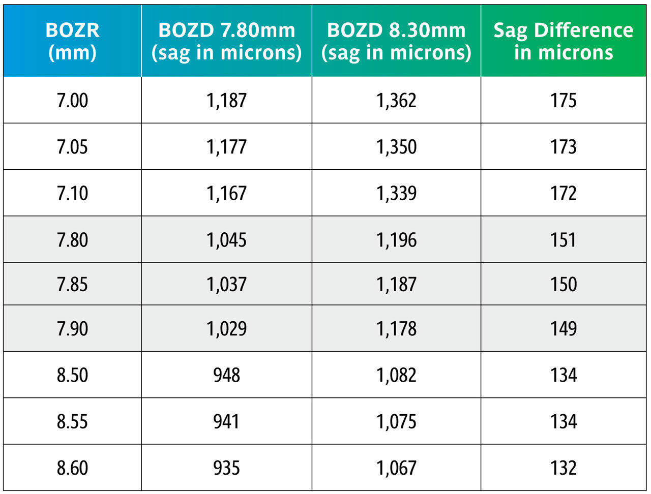
Normal Corneal Curvatures Table 1 shows the change in sagittal (sag) heights across the normal range of corneal curvature when the BOZD is changed by 0.50mm using typical values of 7.80mm to 8.30mm and using three radii for each level.
It can be seen in Table 1 that changing the BOZD by 0.5mm for typical BOZR and two BOZDs results in a large change in sag, which would significantly change the fit of the lens. However, the wider BOZD is then affected by the corneal eccentricity, and this is discussed later.
Using the sag figures from Table 1, Table 2 shows what happens in the above examples but now comparing the sag changes when varying the BOZR in 0.05mm steps.
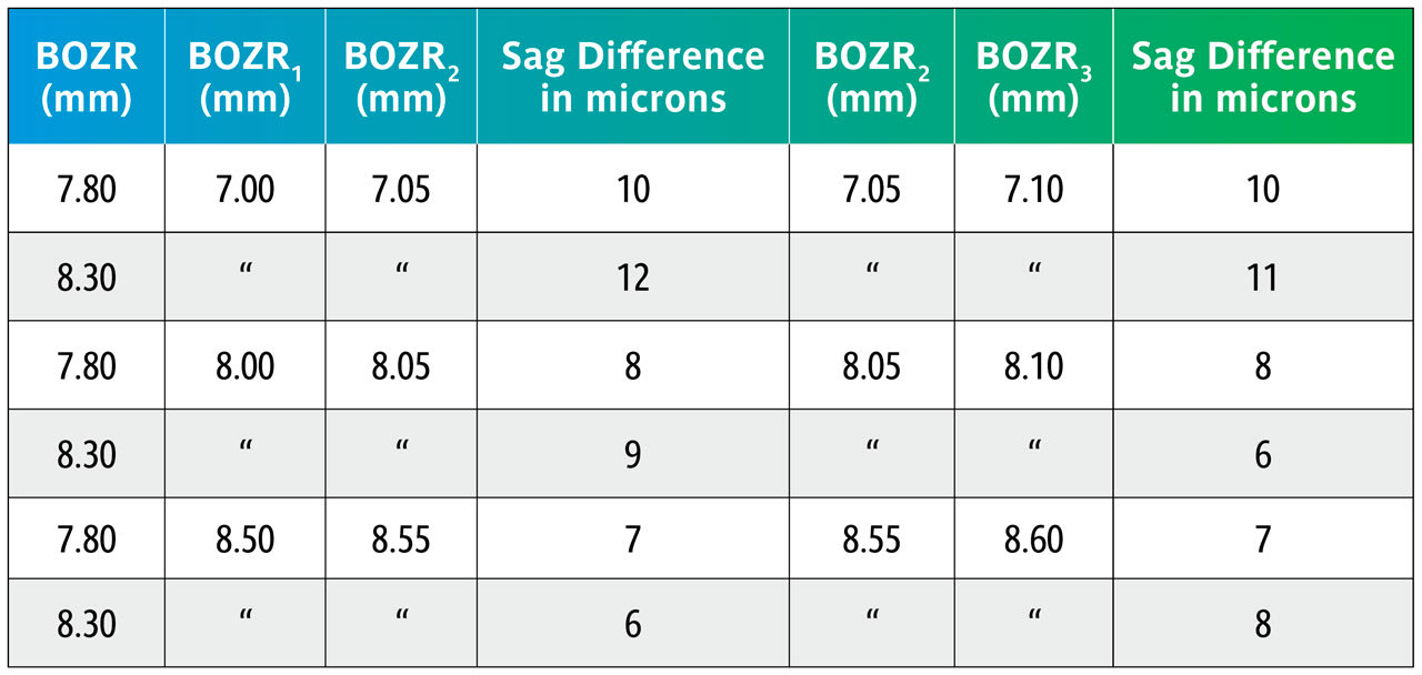
The data in Table 2 shows that varying the BOZR by 0.05mm steps changes the central lens sag by 6µ to 12µ with an average of 9µ.
In a clinical situation, a change of 9µ becomes clinically significant and can, for example, change an apparent “aligning” BOZR to one showing slight apical clearance. Equally, reducing the lens sag by 9µ will reduce an “ideal” fit to one that is slightly flat. It should also be noted that a greater change is apparent as the cornea steepens.
Keratoconus Keratoconic lenses generally differ from normal GP lenses in that they are steeper, have a wide peripheral bearing surface, and therefore a smaller BOZD, typically around 6.00mm to 6.50mm.
Here we repeat Table 1 but now with BOZRs of 5.00mm, 5.50mm, 6.00mm, 6.50mm, and 7.00mm and BOZDs of 6.00mm and 6.50mm.
Once again, the change in BOZD results in a significant change in sag. Although this would significantly affect the fit, it would not be as great as shown due to further settling back on the keratoconic cornea.
Again, using the sag figures from Table 3, the effect of changing the BOZR in 0.05mm steps can be calculated and are shown in Table 4.
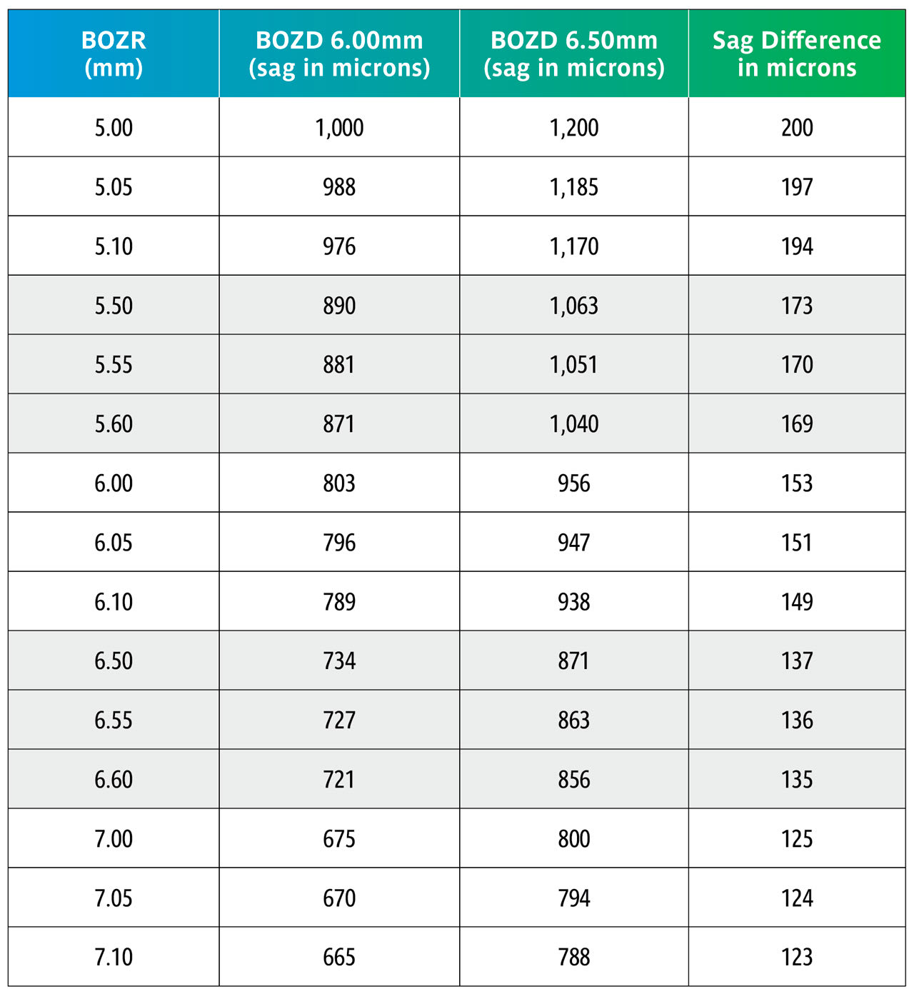
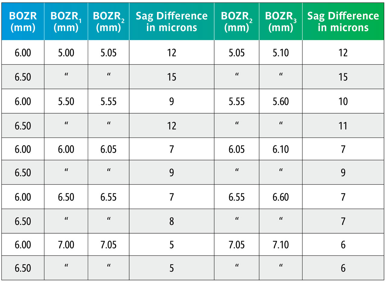
Table 4 again uses the sag calculations from Table 3 to show the sag variations with the same BOZDs but changing the BOZR in 0.05mm steps.
This shows that changing the BOZR in 0.05mm steps, and with typical BOZDs for keratoconic lens designs, produces a change in sag from 5 to 15 microns.
Practitioners can utilize these sag calculations to determine the change in BOZR necessary when the BOZD is changed. From these, it is possible to determine simple RoT to help guide the student or novice practitioner and to make more logical judgments when selecting the next trial lens or to refine a lens fit. Unlike simply looking at the central tear layer thickness (TLT) at the lens apex and how this changes with BOZR, changing the BOZD involves assessing the effect of the corneal eccentricity (e) and how this affects lens sag.
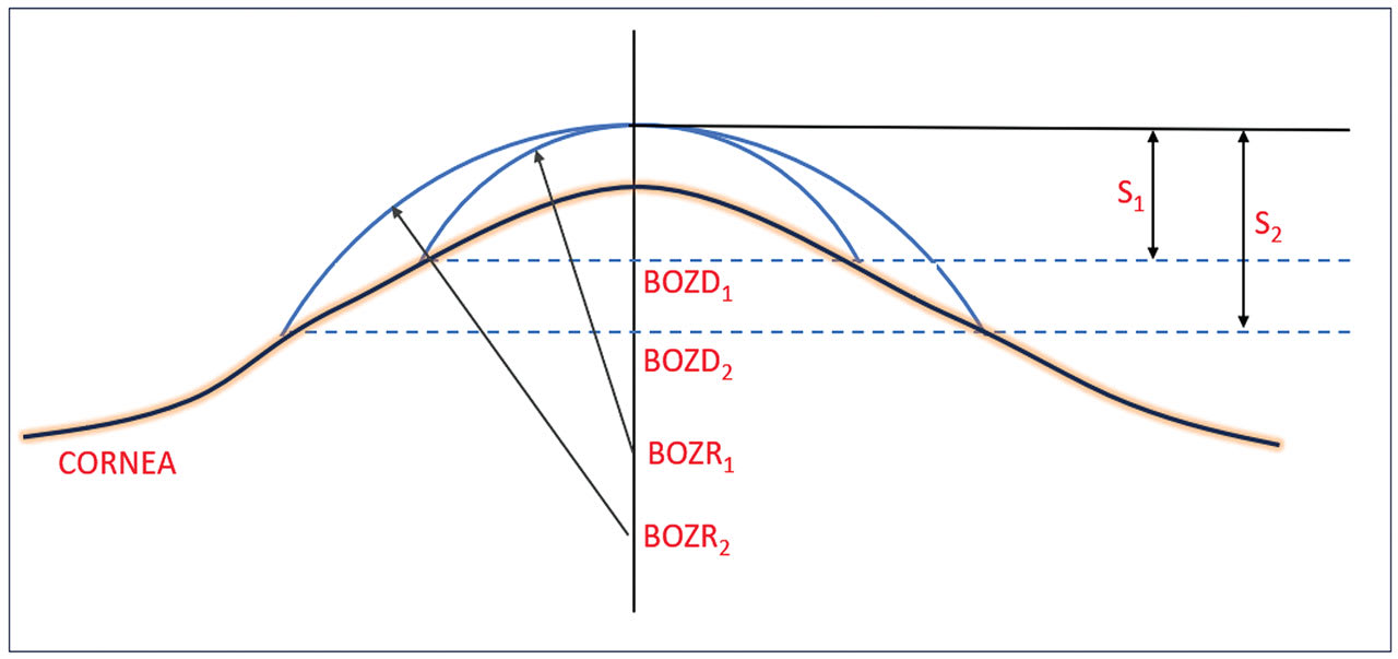
This situation is shown diagrammatically in Figure 2. In this situation, the practitioner has found the “ideal” fitting lens with a BOZR1 which gives sag S1. However, the practitioner felt that the lens BOZD1 was too small and decided to increase the BOZD1 to BOZD2 by (a typical) 0.5mm. However, the flattening of the cornea (represented by its e value) indicates that the BOZR must be flattened in this example to give the same lens apex and with a sag shown by S2.
As the BOZR is changed to amend the fit, this changes the shape and, therefore, the power of the liquid tear lens trapped between the cornea and back lens surface. This also requires a compensatory change in the lens power. The change in liquid lens power for BOZR changes of 0.05mm over the normal corneal and keratoconic ranges have, therefore, been calculated and provide a further RoT.
To determine this, the sag of the aspheric cornea, and using BOZD2 as specified by the practitioner, is determined using the following equation:
To determine this, S2 is calculated using the following equation:
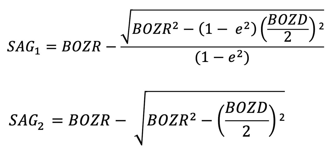
Sag (S2) can then be used to calculate the new spherical central curve (BOZR2).
It should be emphasized that for the sake of simplicity, we are only looking at the BOZR; the peripheral curves having been ignored but assumed that flattening (or steepening if reducing the BOZD) of these curves has been incorporated as part of the trial set design.
The results are shown in Tables 5 and 6. Table 5 shows nominated BOZRs of 7.20mm, 7.80mm, and 8.40mm to represent the typical spread of normal corneal radii. BOZDs of 7.80mm, 8.30mm, and 8.80mm have been chosen to represent the typical spread of central curve diameters, and three values of e as 0.30, 0.45, and 0.60 as again representing the typical spread of corneal eccentricity values.
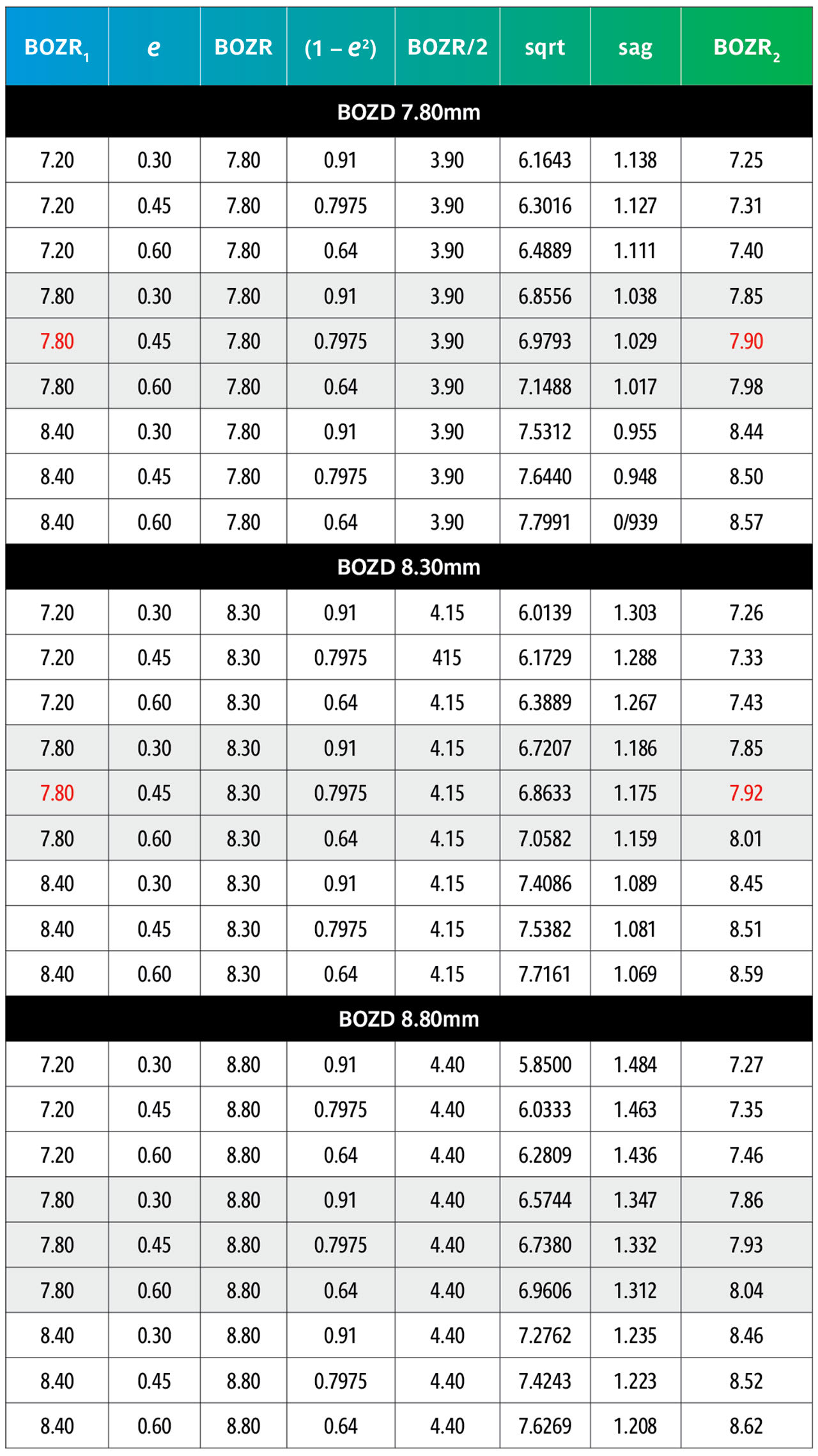

By comparing an original BOZR1 (first column) in one block with the same BOZR1 and e value, but a larger or smaller BOZD, it is possible to obtain the new radii (BOZR2). In Table 5, an example is shown in red for a BOZR of 7.80mm and an e value of 0.45. The original radius selected was 7.80mm with a BOZD of 7.80mm but becomes 7.92mm for a BOZD of 8.30mm.
Reversing the figures would give the same result if a smaller BOZD was desired.
From Table 6, it can be observed that the change to BOZR2 required varies little over the range of normal corneal values shown as BOZR1 but varies more significantly across the range of corneal eccentricities.
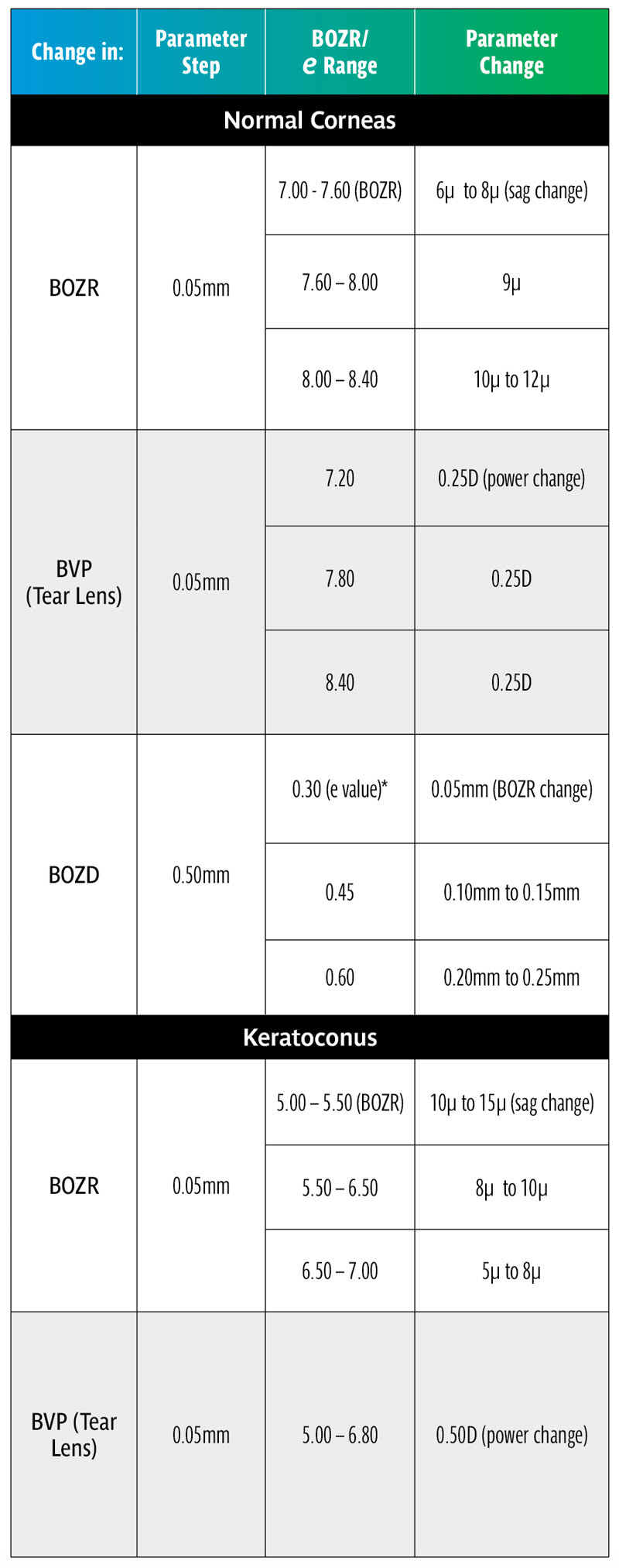
Thus, increasing or decreasing the BOZD by 0.50mm requires a change in BOZR of approximately 0.05mm for low corneal eccentricity values, 0.10mm to 0.15mm for midrange e values, and 0.20mm to 0.25mm for steep corneal eccentricities. This then provides a guide when selecting a new trial lens with a different BOZD (and logically an equally larger or smaller TD trial lens).
COMPENSATORY POWER CHANGES FOR CHANGES IN BOZR
As the fit of a GP lens is changed, so too is the shape of the liquid lens trapped between the cornea and the lens back surface. As this fluid layer has an optical power, as the liquid lens is changed so too must the lens BVP also be changed to compensate. Thus, a steepening of the BOZR will increase the positive power of the liquid lens; there must, therefore, be a negative change made to the lens BVP to compensate for this and vice versa.
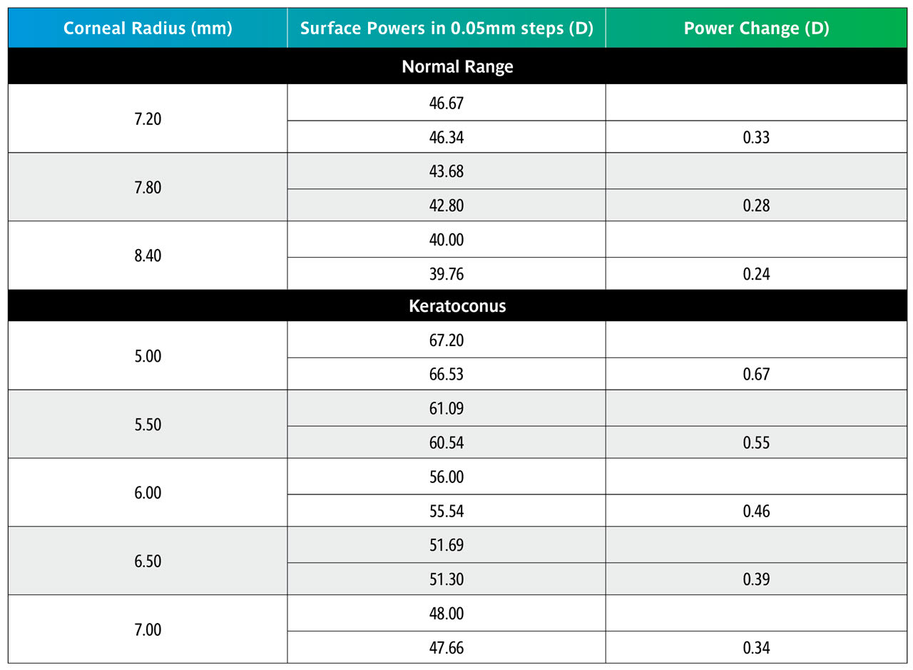
The change in liquid lens BVP is given by the formula below, where BOZR1 and BOZR2 represent the two radii. In Table 3, the change is represented by a change in radius of 0.05mm (e.g., from 7.80mm to 7.85mm).

Table 7 shows that over the normal range of corneal curvature, changing the BOZR by 0.05mm produces a change in the liquid lens power of 0.25D. Over the keratoconic range, this increases to approximately 0.50D.
RULES OF THUMB SUMMARY
• A typical clinical change of 0.50mm in BOZD produces a very significant change in lens sag requiring a compensatory change in BOZR. It should be noted that this applies over all radii including keratoconus designs.
• Although significant, the effect on fit will not be as extreme as shown in Tables 1 and 3 due to the settling back on the flattening corneas designated by their e value.
• Increasing the BOZD will require a flatter fit and vice versa. For an average e value, a compensatory change of 0.10mm to 0.15mm in BOZR is required (range 0.05mm to 0.25mm, depending on the e value) for every 0.50mm change in BOZD.
• Ideally the trial lens selected should have the estimated BOZD and TD of the final lens.
• Changes in BOZR of 0.05mm produce a useful clinical change in lens sag, varying from 6 to 12 microns, for the normal range of corneal curvature with an average change of 9 microns.
• For keratoconic lenses, the sag changes vary from 5 to 15 microns with BOZR changes of 0.05mm.
• The change in sag is greater for steeper BOZR (and vice versa), both for the normal corneal radii range as well as the keratoconic range of radii and should be remembered when changing trial lenses.
• Logically, fitting sets should be in regular micron sag steps rather than regular radii changes. However, as most corneal radii are in the middle range of “normal,” the sag change is around 9µ and therefore a useful practical step.
• However, in the keratoconic range of corneal radii, changes in regular BOZR steps can result in significant change variation in sag across the range of keratoconic corneas. Although unlikely to be put into practice, keratoconic fitting lenses should, in theory, have variable radii adjusted to give a fixed sag change, say 10µ, at each step.
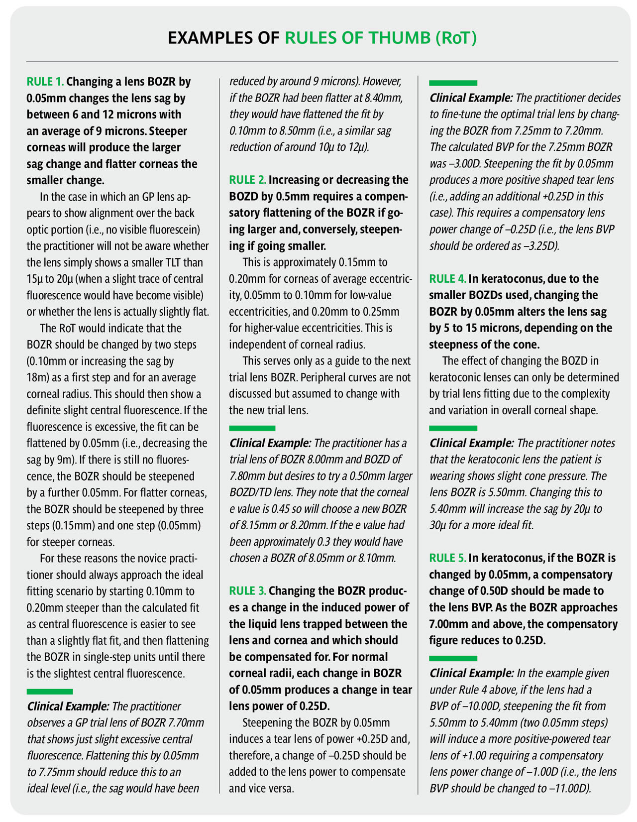
It is now possible to work out several Rules of Thumb. It should be emphasized that RoT are not scientifically accurate but serve to simply guide the practitioner to the next step (e.g., the next trial lens or to refine a lens fit). The range of variables make accurate advice impossible, and this includes the possible inaccuracies taken in the original ocular measurements. Nevertheless, they can save useful time in a busy practice situation and serve to check on the accuracy of other measurements. It should be emphasized that RoT are generally only applicable to small clinical changes, larger changes requiring accurate calculation. Table 8 summarizes the RoT and clinical examples can be found in the sidebar below.
Acknowledgment: The authors wish to express their thanks to associate professor Ranjay Chakraborty, of Flinders University, and associate professor Rod Watkins, formerly of Flinders University, for their help in the preparation of this paper.
REFERENCES
1. Rule of Thumb. Wikipedia. Available at en.wikipedia.org/wiki/Rule_of_thumb. Accessed 2024 Jul 17.
2. Phillips AJ. Rigid Gas Permeable Corneal and Corneoscleral Lens Fitting. In Contact Lenses. Phillips AJ, Speedwell L, eds. London, Elsevier. 2019 Feb 22:175-206
3. Guillon M, Sammons WA. Contact Lens Design. In Contact Lens Practice. M. Ruben M, Guillon M, eds. London, Chapman and Hall Medical. 1994:87-103.


